Force and Pressure
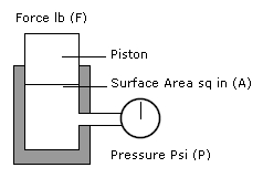
Fluid is pressurised by the FORCE of a piston. The piston moves in a cylinder which is sealed to prevent fluid leaking out or air entering into the system. The piston must move with little friction in the cylinder as this will have an adverse effect on the system.
There is air on one side of the piston and hydraulic brake fluid on the other side. The area of each piston is determined using the PiR2 formula. To obtain a measurement in inches from millimetres simply multiply the millimetres by 0.03937. You then divide the Diameter (D) by 2 to obtain the Radius (R) of the Piston and then calculate the piston area in square inches by using the PiR2 formula. For example:
| Piston Diameter (D) | Piston Diameter (D) | Piston Radius (R) | Piston Surface Area (A) |
| 14mm | 0.551" | 0.275" | 0.238 in2 |
| 15mm | 0.590" | 0.295" | 0.273 in2 |
| 16mm | 0.629" | 0.314" | 0.311 in2 |
| 17mm | 0.669" | 0.334" | 0.351 in2 |
| 18mm | 0.708" | 0.354" | 0.394 in2 |
| 19mm | 0.748" | 0.374" | 0.439 in2 |
| 20mm | 0.787" | 0.393" | 0.486 in2 |
Now that we have this figure we can start calculating other measurements.
F - Force on Piston (lbf) / A - Area of Piston (in2) = P - Hydraulic Pressure (psi)

The amount of pressure depends on how much FORCE you put on the piston.
If the piston in the above system has an area of 2 in2 and the FORCE is 400lbf then the pressure is calculated using the formula as follows:
400 (lbf) / 2 (in2) = 200 (psi)
A smaller piston gives a higher pressure. If you replaced the piston with only a 1 in2 area in the same system with 400lbf of FORCE then the pressure exerted is 400 psi. Pistons can be used to multiply the FORCE in a hydraulic system. By choosing pistons with different surface areas any relationship with FORCE is possible.
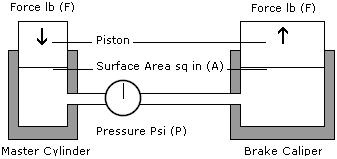
A simple hydraulic braking system on a motorcycle is shown below. The pistons in this system have two different surface areas with the master cylinder piston having a surface area of 2 in2 and the piston in the caliper has a surface area of 4 in2. With the same 400lbf of FORCE being applied to the master cylinder the piston produces 200 psi. Remembering the hydraulic laws we discussed earlier:
- Fluid cannot be compressed to a lesser volume, no matter how high the pressure.
- Pressure is equal over all surfaces of the containing system.
When looking at the two hydraulic laws above we know that the 200 psi in our example system will act equally on all surfaces within the system. The shell of the master cylinder, the shell of the caliper and the hoses that connect them both will have 200 psi acting upon them but they cannot move. However the piston at the caliper is able to move and will have the same 200 psi acting upon it.

As this piston has a 4 in2 surface area the FORCE it produces will be 800lbf. The area has doubled so the FORCE is doubled. 400lbf of FORCE is pushed down onto 2 in2 which then acts upon the 4 in2 surface. We must remember that only the FORCE changes in this system – the pressure remains the same at 200 psi. This is 2 in2 so with the other piston having 4 in2 the FORCE produced has twice the surface area to work upon and so twice the FORCE in lbs.
To increase the FORCE on the caliper piston we can decrease the area of the master cylinder piston area or increase the surface area on the caliper piston. The reverse is true to decrease FORCE on the caliper piston. We can either increase the area of the master cylinder piston area or decrease the surface area on the caliper piston.
So that covers the FORCE at work in your braking system and we know that by decreasing or increasing parts of the system you can alter the FORCE produced at the caliper but that does not increase pressure. Pressure is the constant in the braking system and cannot be altered internally. If you can produce 200 psi at the master cylinder hydraulic law requires that 200 psi is produced at the caliper.
